Creating Inter-aggregate Links
Overview:
In this experiment you will learn how to draw topologies that connect nodes at different aggregates (in different geographic locations). We will use the following network topology for this experiment:

|
|
Prerequisites:
For this tutorial you need :
|
Tools:
We will use the following tools:
|
|
Where to get help:
- Contact your TA and/or Professor for help. If you are doing this exercise outside the context of a course, please email help@geni.net
|
 |
1. Verify your Environment Setup:
This exercise assumes you have already setup your account at the GENI Portal. In particular ensure that:
- You can login to the GENI Portal
- You are a member of a GENI Project (there is at least one project listed under the ''Projects'' tab)
- You have setup your ssh keys (there is at least one key listed under the ''Profile->SSH Keys'' tab)
2. Setup the Topology:
- Login to the GENI Portal
- Create a new slice with the name of your choice.
- Click the Add Resources button on the Slice page.
- Drag two VMs (the black icons) onto the canvas.
- Draw a link between them.
- Drag a second site onto the canvas.
- Drag one of the existing VMs to the second site.
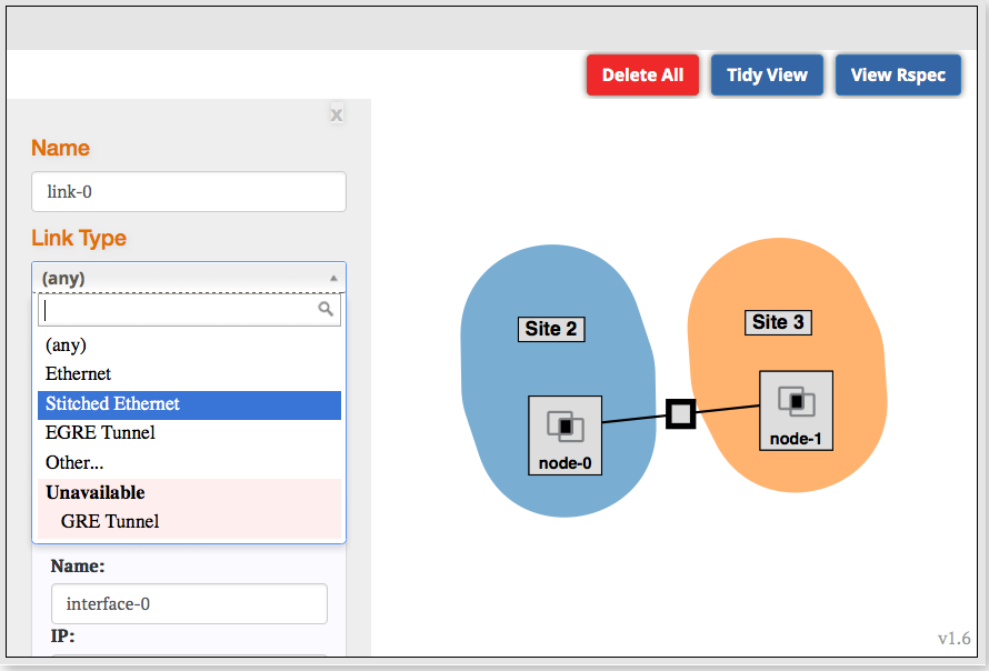
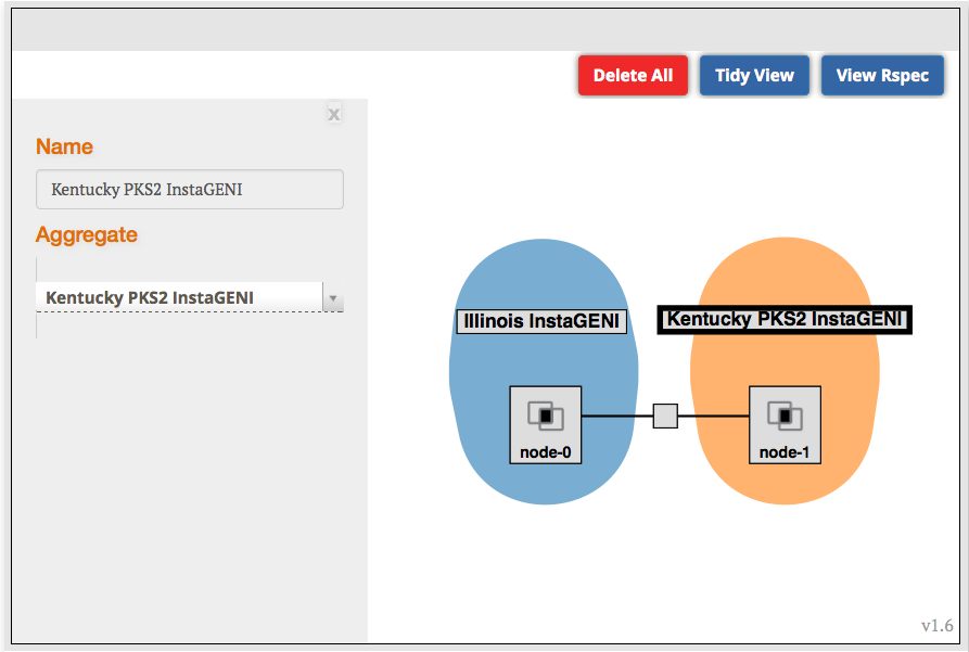
- Click on the unlabeled box in the middle of the link. Select "Stitched Ethernet" as the link type.
|

Figure 1 Set the Link Type on the inter-aggregate link.
|

|
The link type you select will affect the aggregates you are allowed to bind to in the next step.
- Stitched Ethernet gives you a layer 2 link (i.e. a VLAN) between aggregates.
- EGRE Tunnel gives you a layer 3 tunnel between aggregates.
- However, if you would like a Layer 2 link connecting only ExoGENI sites, instead set the Link Type to "(any)" and pick any two ExoGENI aggregates except "ExoGENI ExoSM".
|
- Bind each site to an aggregate. (If you are doing this as part of a tutorial, use the aggregates specified on your worksheet.)
- Click the Auto-IP button (it is below the Jacks pane). This will ensure that there are IP address assigned to the links.
- Click Reserve Resources.
|

Figure 2 Bind the sites. The aggregate choices will be limited based on the link type.
|
- The reservation may take a couple of minutes to complete. After the reservation completes, return to the slice page.
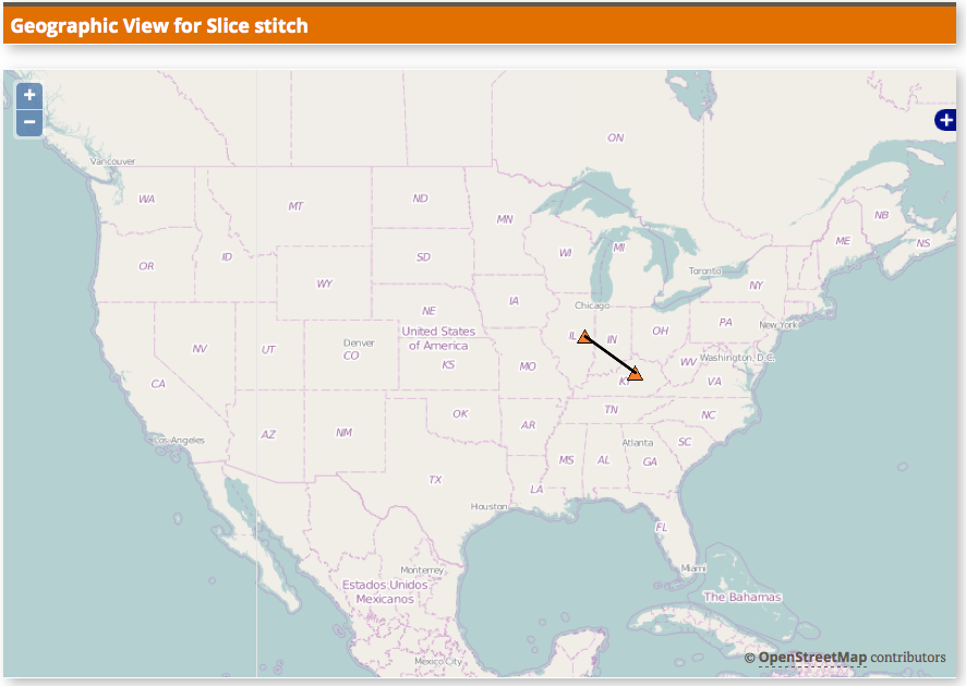
- While you are waiting for the nodes to be ready, click the Geo Map button. Wait for this page to load to see where your nodes are geographically located. Note that it may take a moment for your nodes to be drawn.
|

Figure 3 The geographical location of your nodes.
|
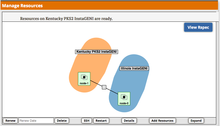
- Press the back button on your browser to return to the slice page. Wait for the nodes to be ready.
|

Figure 4 The stitched topology is ready and green.
|
|
 |
3. Test Connectivity
- Log into one of the nodes and ping the data plane interface of the other node. Reminder: To figure out the IP address of the other node, either look at the properties of the link on the Slice page OR log in to the other node and run `/sbin/ifconfig`.
|
4. Cleanup
After you are done with the exercise, delete your resources:
- Click on a blank part of the canvas, then press the Delete button. When prompted, confirm you want to delete all of the resources in the slice.
- After a few moments all the resources will have been released and you will have an empty canvas again.
|
