
| Version 48 (modified by , 10 years ago) (diff) |
|---|
NOTE: NLR is in the process of being shut down. GENI has moved connections off of NLR, but we are in the process of updating documentation.
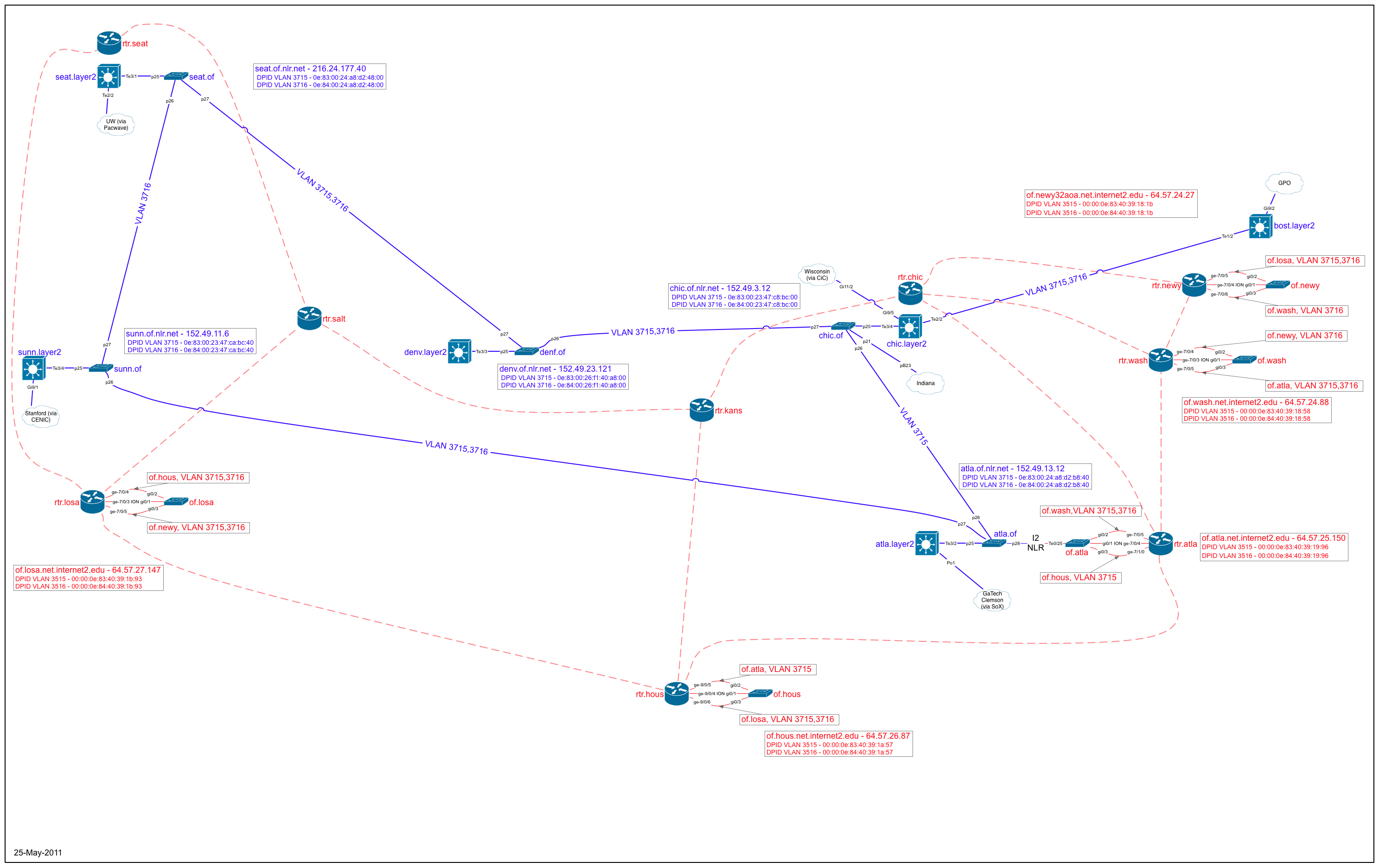
The initial Spiral 3 GENI network core is a set of OpenFlow-capable switches in NLR and Internet2.
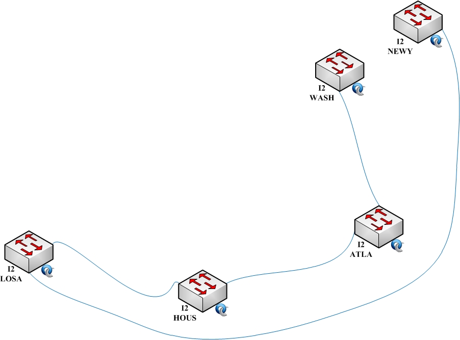
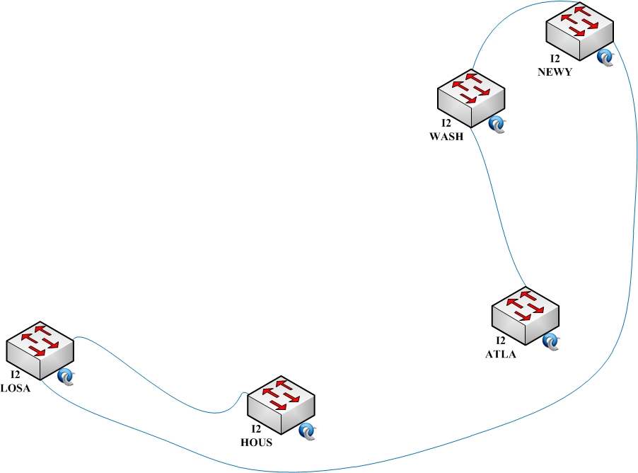
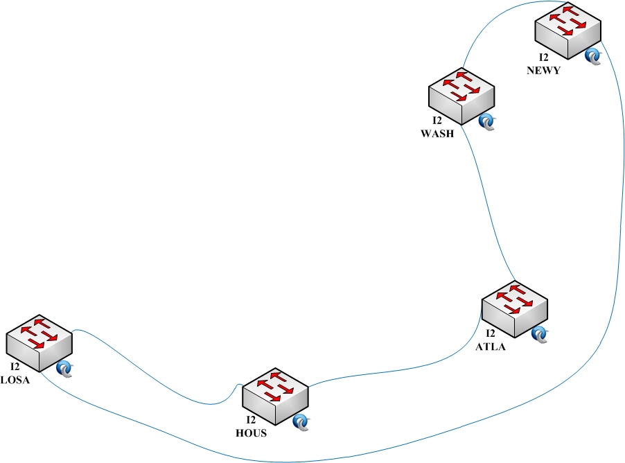
There are currently three standing backbone interconnect VLANs (3715, 3716, and 3717) carried on the ten switches in the core, which are located in the nine cities shown on the maps below. Two of the VLANs in each provider are topologically a broken ring (to help prevent accidental loops), with the two rings in each VLAN linked in Atlanta. The third VLAN (3717) is a ring within each provider. The gap in each of the broken-ring VLANs is between two different links, to provide either a longer or shorter path through the core between two switches. The three VLANs are not interconnected in the core, and should not extend beyond the backbone providers into regionals or campuses.
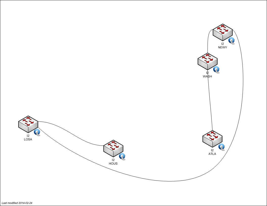
VLAN 3715

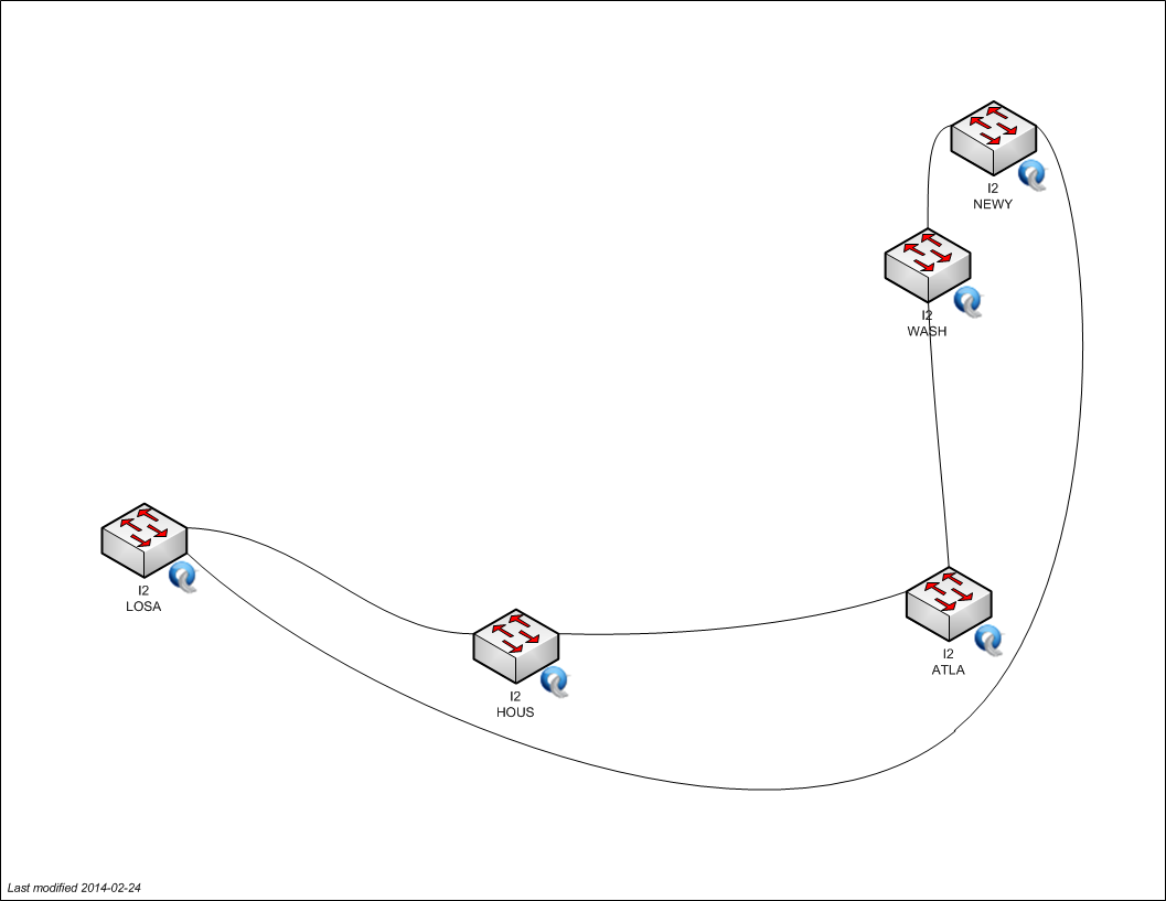
VLAN 3716

VLAN 3717

Testing / monitoring
We're in the process of setting up a process for testing the OpenFlow core from end to end, including out to campuses. VLAN 3715 has four endpoints, and VLAN 3716 has two, which we intend to connect to these campuses:
| VLAN | OpenFlow Connector | Participant | Host IP |
| 3715 | WASH I2 | Rutgers | 10.37.15.145 |
| 3715 | NEWY I2 | BBN | 10.37.15.102 |
| 3715 | SEAT NLR | Washington | 10.37.15.90 |
| 3715 | SUNN NLR | Stanford | 10.37.15.3 |
| 3716 | HOUS I2 | KSU | 10.37.16.113 |
| 3716 | CHIC NLR | Indiana (Gigapop) | 10.37.16.49 |
The core network status page at BBN shows whether test hosts at BBN and Stanford can ping the other test hosts right now.
For a complete list of known hosts in the connectivity subnets of these VLANs see:
Backbone Integration
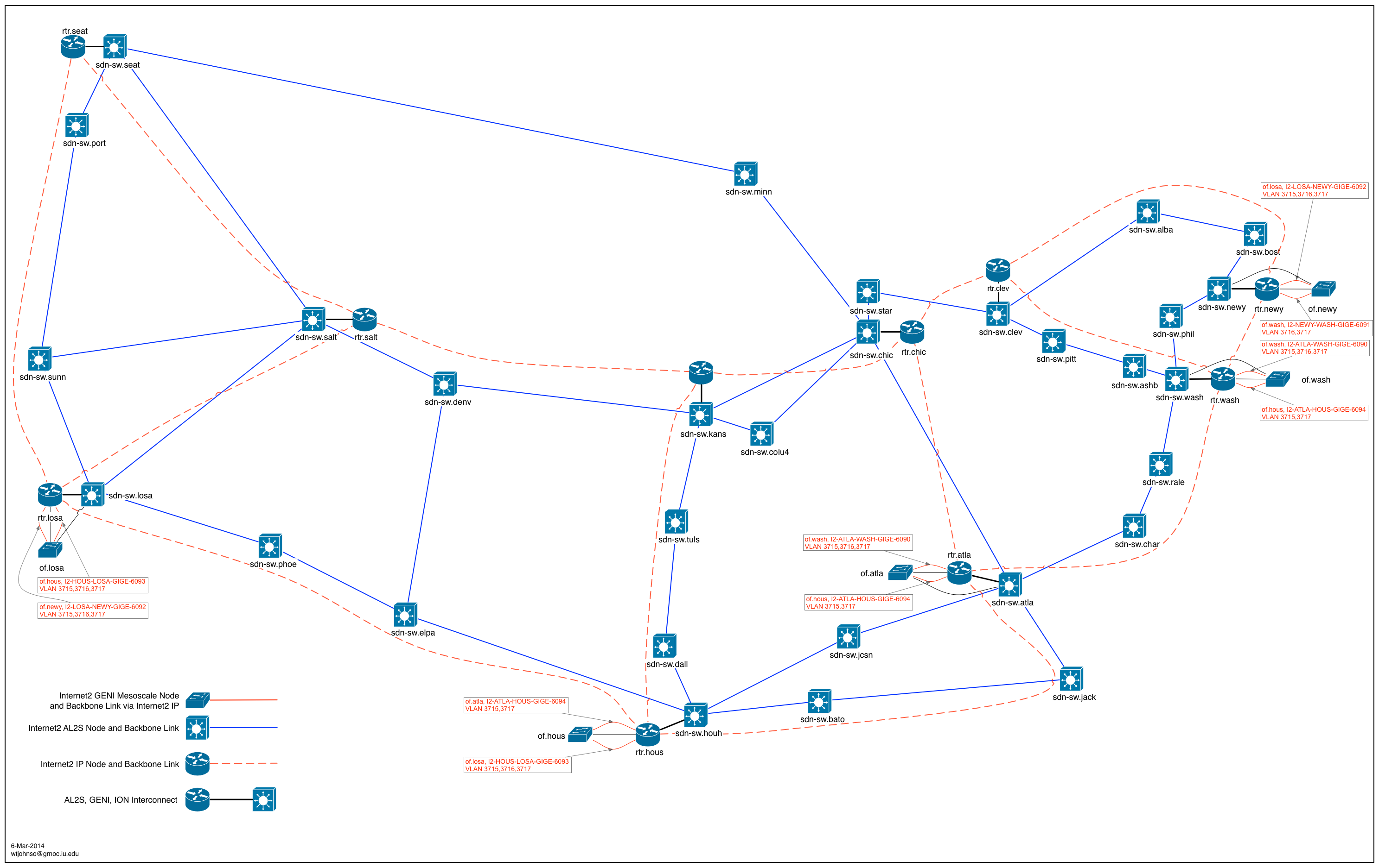
Click the picture below for the full-sized image.

Note: Network Diagrams maintained by GMOC, historical revisions can be found here - http://gmoc.grnoc.iu.edu/gmoc/file-bin/geni-network-diagram.html
OpenFlow Core entry-points
Note, the OpenFlow Core Entry-points are available from the diagram above. The diagram is the authoritative source of information but is listed below for easier review.
| Site | backbone "exit port" | Openflow "entry port" |
| GeniSite/Washington | NLR seat.layer2[Te3/1] | NLR seat.of[p25] |
| GeniSite/Stanford | NLR sunn.layer2[Te3/4] | NLR sunn.of[p25] |
| GeniSite/GeorgiaTech | NLR atla.layer2[Te3/2] | NLR atla.of[p25] |
| GeniSite/Clemson | NLR atla.layer2[Te3/2] | NLR atla.of[p25] |
| GeniSite/BBN | NLR chic.layer2[Te3/4] | NLR chic.of[p25] |
| GeniSite/Wisconsin | NLR chic.layer2[TE3/4] | NLR chic.of[p25] |
| GeniSite/Indiana | N/A | NLR chic.of[p21] |
| GeniSite/Rutgers | I2 rtr.wash[ge-7/0/3] | I2 of.wash[gi0/1] |
| GeniSite/BBN | I2 rtr.newy[ge-7/0/4] | I2 of.newy[gi0/1] |
Cross Connect
The "cross-connect" between I2 and NLR in ATLA connects via I2 OF Atla, Te0/25 facing NLR OF Atla, port 28.
Note: atla.layer2.nlr.net[Te3/2] Is the port facing the NLR ATLA OpenFlow switch, in this sense, this port is the FrameNet endpoint.
VLAN Translation
The shared mesoscale VLAN in the core uses loopback cables for VLAN translation where needed. Some of those VLANs are not experimenter controlled, but rather are used for isolated transport to a specific site. On the NLR and Internet2 core switch, the Layer1Transport software is used to pass that traffic along at layer 1, similar to how a psuedowire would work.
Attachments (17)
-
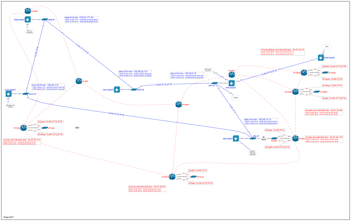
OF-INT-BB--11-Apr-2011.png (486.7 KB) - added by 13 years ago.
Openflow Core deployment map showing switchports and backbone integration
- OF-INT-BB 18-May-2011.png (584.4 KB) - added by 13 years ago.
- OF-INT-BB_18-May-2011.pdf (72.4 KB) - added by 13 years ago.
-
OF-INT-BB 25-May-2011.png (584.3 KB) - added by 13 years ago.
new backbone diagram for May 25, 2011
-
OF-INT-BB 25-May-2011.pdf (72.3 KB) - added by 13 years ago.
new backbone diagram for May 25, 2011
-
OF-INT-BB 10-May-2011.png (245.4 KB) - added by 13 years ago.
adding May 10 BB diagram for historical purposes
-
OF-INT-BB 10-May-2011.pdf (72.0 KB) - added by 13 years ago.
adding May 10 BB diagram for historical purposes
- OF-INT-BB 30-Jun-2011.pdf (72.7 KB) - added by 13 years ago.
- OF-INT-BB 30-Jun-2011.png (588.4 KB) - added by 13 years ago.
- geni-core-vlan-3715.png (57.9 KB) - added by 10 years ago.
- geni-core-vlan-3716.png (57.6 KB) - added by 10 years ago.
- geni-core-vlan-3717.png (58.3 KB) - added by 10 years ago.
- geni-core-vlan-3715-v2.jpg (95.3 KB) - added by 10 years ago.
- geni-core-vlan-3716-v2.jpg (93.9 KB) - added by 10 years ago.
- geni-core-vlan-3717-v2.jpg (98.3 KB) - added by 10 years ago.
- OF-INT-BB 28-Mar-2014.pdf (100.6 KB) - added by 10 years ago.
- OF-INT-BB 28-Mar-2014.png (614.1 KB) - added by 10 years ago.