
| Version 3 (modified by , 13 years ago) (diff) |
|---|
4. GENI WiMAX base station configuration and experiment use cases
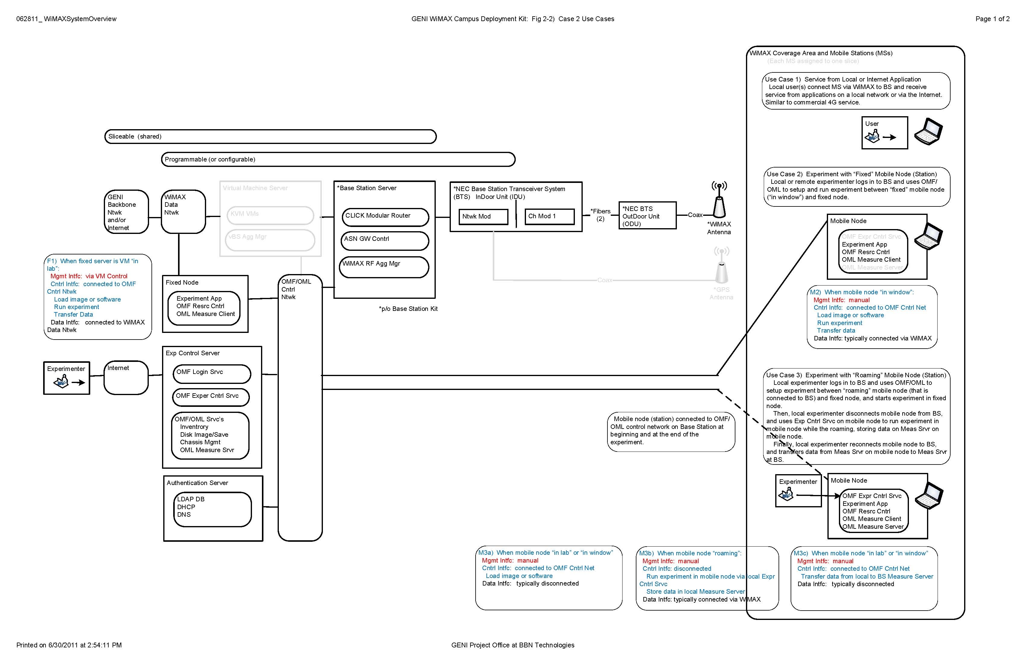
The GENI WiMAX base station configuration is shown in the following drawing, and summarized in base station configuration.

The WiMAX base station (BS) includes:
- NEC base station transceiver system (BTS) indoor and outdoor units, with connections from the outdoor unit to the antenna.
- Base station server, that hosts the data path software
- Data network, that connects data path to the GENI backbone network.
- Experiment control server, that holds the OMF/OML software necessary for experiment control, and includes an Internet connection for experimenters to access the base station.
- Authentication server, that holds the services necessary to control access to the base station by experimenters; these services are separate from the experiment control server to assure better security.
- Control network, that carries control messages within the base station, between the base station, experiment control and authentication servers.
Each base station is installed at a campus site by the PI/staff, and operated for use by local and/or remote experimenters.
In addition there are one or more WiMAX-connected mobile station (MS) nodes, and there are typically one or more fixed nodes (contained within the BS).
There are three use cases which each base station should support:
- Use Case 1: Service from a local or Internet application
- Use Case 2: Experiment with a “fixed” mobile node/station using OMF/OML
- Use Case 3: Experiment with a “roaming” mobile node/station using OMF/OML
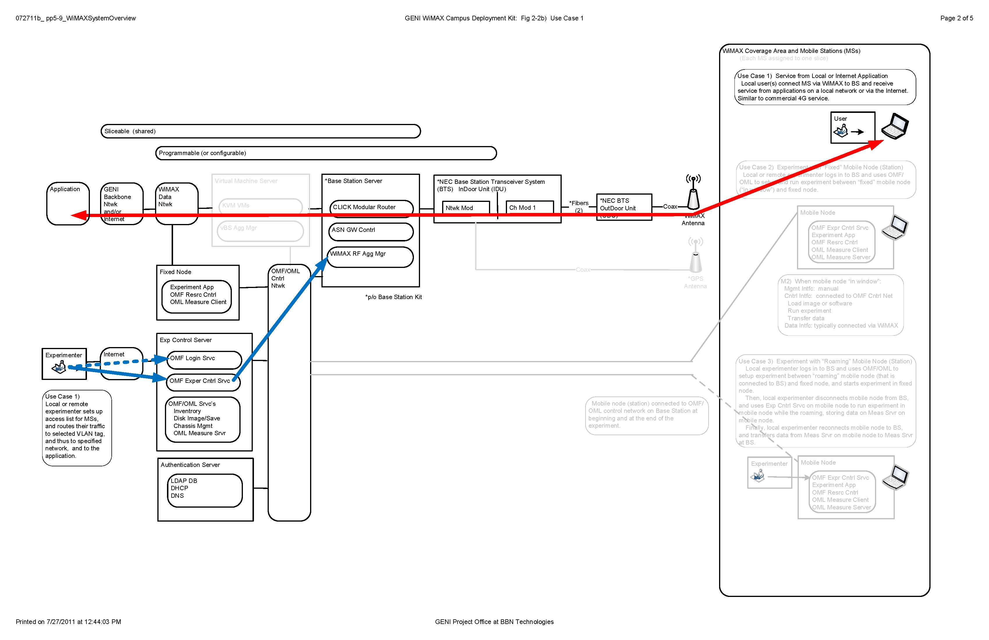
Use Case 1: Service from a local or Internet application
This use case is illustrated in the following drawing.

A local user(s) connects a mobile station (MS) via WiMAX to the base station (BS), and receives service from an application on a local network (i.e., the WiMAX data network), the GENI backbone, or via the Internet. This is similar to commercial 4G service, but restricted to the campus area.
One variation: the application on the local network could be an experiment that does not use OMF/OML for control.
One extension: Such a service arrangement could be done simultaneously at several sites, offering service from an application on the GENI backbone network to users on multiple campus sites.
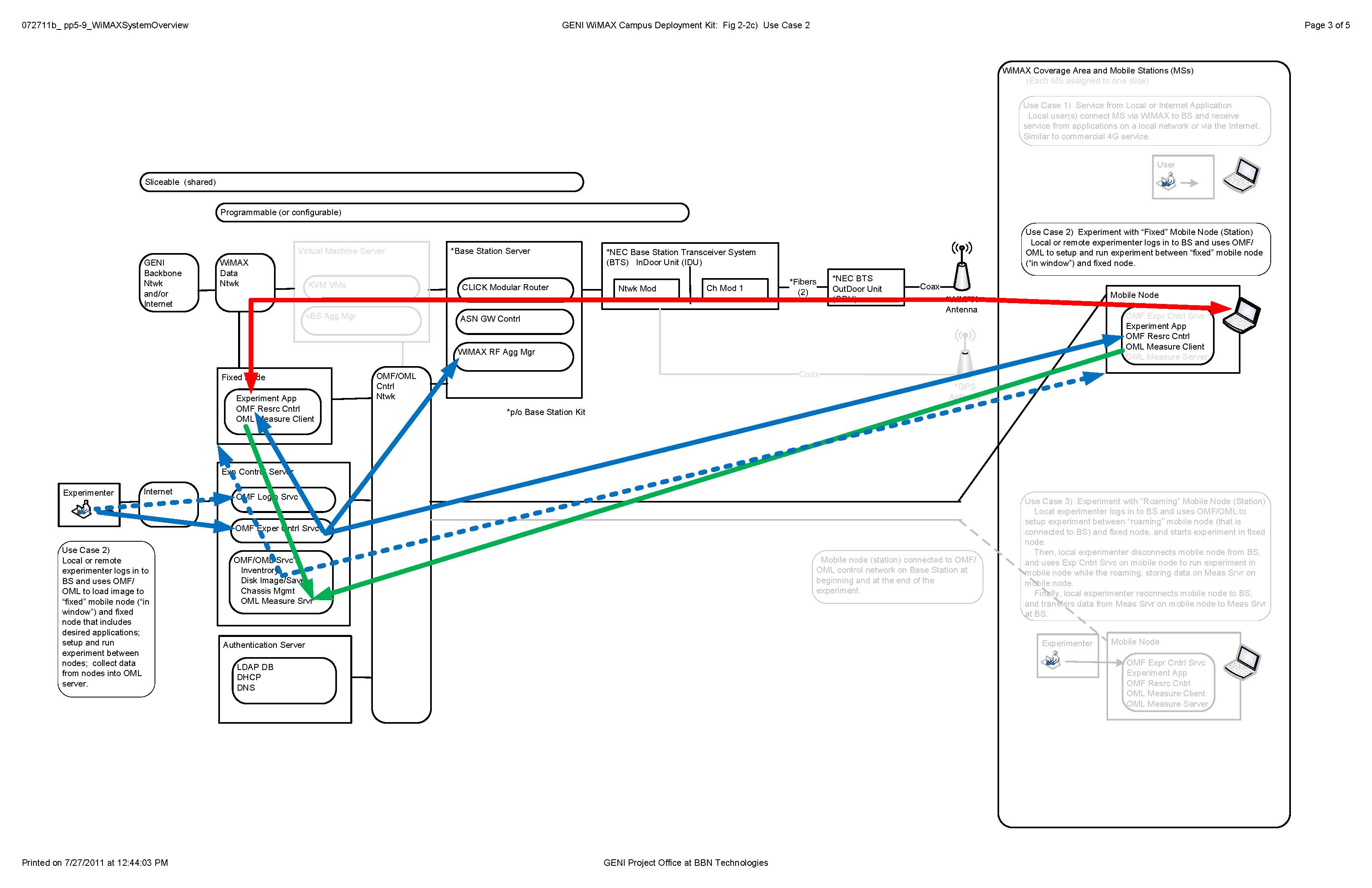
Use Case 2: Experiment with a “fixed” mobile node/station using OMF/OML
This use case is illustrated in the following drawing.

A local or remote experimenter logs into a BS, and uses uses an Ex Cntrl Srvc on the BS to setup and run experiment between “fixed” mobile node (such as one mounted “in a window”, or one connected to a BS by an RF attenuator) and a fixed node (within the BS). All data is collected in a Meas Srvc on the BS.
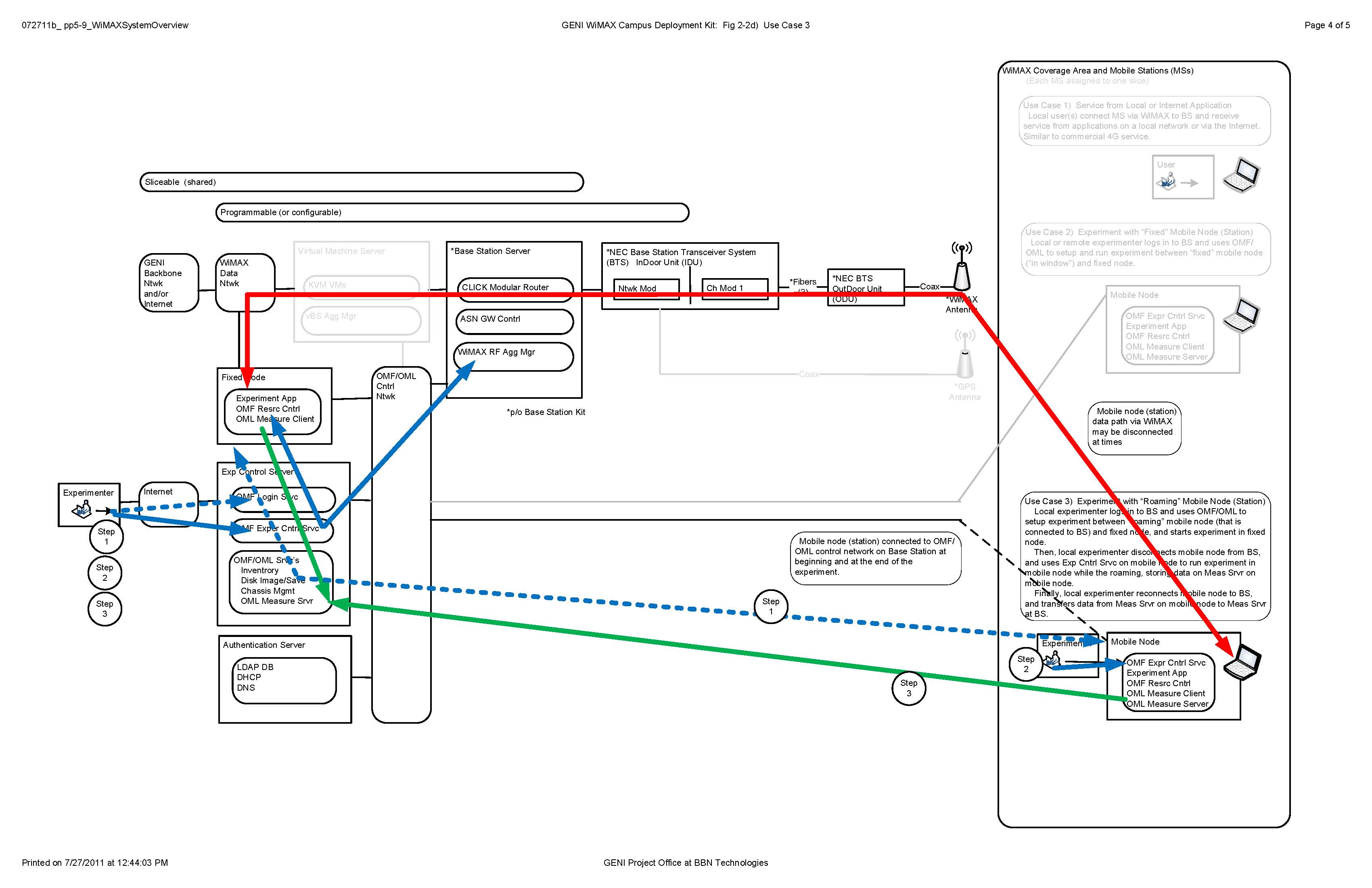
Use Case 3: Experiment with a “roaming” mobile node/station using OMF/OML
This use case is illustrated in the following drawing.
The roaming image for iperf unidirectional experiments is available at http://wimax.orbit-lab.org/downloads/GPO_omf_unidirectionalexperimentsimage.ndz
The roaming image for iperf bidirectional experiments is available at http://wimax.orbit-lab.org/downloads/GPO_omf_bidirectionalexperimentsimage.ndz

A local experimenter logs into BS, and uses an Ex Cntrl Srvc on the BS to setup the experiment between a “roaming” mobile node (that is connected to BS) and a fixed node (within the BS), and uses the Ex Cntrl Srvc start the experiment. Then, the local experimenter disconnects the mobile node from the BS, and uses an Exp Cntrl Srvc on the mobile node to run the experiment in the mobile node while the roaming, storing data on a Meas Srvr on the mobile node.
While roaming, the local experimenter can interact with the Exp Cntrl Srvc to guide the experiment, i.e., to command that data be taken at a particular location. In addition, the Visualization Srvc running on the mobile node can be used to observe the ongoing measurement. Finally, the local experimenter reconnects the mobile node to BS, and transfers data from the Meas Srvr on the mobile node to the Meas Srvr on the BS, which has been collecting data from the BTS. At the end, all data is contained on the Meas Srvc on the BS, which can now be processed and plotted.
One variation: The Exp Cntrl Services on the BS and MS operate independently, and the experiment is started in both, without a connection between the MS and the BS. At the end of the experiment, data from the two Meas Srvc's may, or may not, be explicitly merged.
Attachments (4)
- Visio-062811b_pp5-6_WiMAXSystemOverview_Page_1.jpg (855.2 KB) - added by 13 years ago.
- Visio-072711b_pp5-9_WiMAXSystemOverview_Page_2.jpg (368.8 KB) - added by 13 years ago.
- Visio-072711b_pp5-9_WiMAXSystemOverview_Page_3.jpg (403.9 KB) - added by 13 years ago.
- Visio-072711b_pp5-9_WiMAXSystemOverview_Page_4.jpg (419.0 KB) - added by 13 years ago.
Download all attachments as: .zip