
| Version 1 (modified by , 14 years ago) (diff) |
|---|
Aggregate Networks
A GENI aggregate provides a network or computing resource to the GENI network. In either case, the aggregate's network must be able to connect to the other GENI aggregates. Each aggregate's network is considered an autonomous system, and the internal configuration is not externally important. However, it is expected that all of an aggregates advertised interfaces are internally connected, ideally at layer 2.
The boundaries of an aggregate are loosely defined. At one school, the regional network, campus network, and departmental networks might each be independent network aggregates. At another, all three might be combined into a single aggregate to provide a simpler interface to the external research community. The campus department might not have administrative control over its regional, but it is at least able to call the regional up and make changes when necessary. The I2 and NLR layer-2 networks (such as I2 DCN, I2 GENI Wave, and NLR FrameNet) are also good candidates for network aggregates as each network is internally connected at layer 2. Other examples include LEARN and the BEN network.
Managing VLANs
Aggregates should connect to GENI at layer 2, which typically requires the use of VLANs. VLANs are used to create multiple broadcast domains on a switched network. Frames that arrive on a switch with a particular VLAN will only be bridged to other interfaces on the switch with the same VLAN id. In order for hosts on different VLANs to communicate they typically use IP and communicate through a router.
Trunk (802.1q) vs Native
If all traffic on an interface is assigned to a single VLAN, then the interface is configured in 'native mode' for that port. The frame is not altered, but the switch knows to only bridge traffic from that port with other ports that are configured for the same VLAN.
However, if traffic for multiple VLANs needs to traverse a single interface, the VLAN id needs to be added to each frame. This tag is defined in IEEE 802.1q and is called a tagged interface (or trunk).
Coping with limited VLAN space (VLAN Mapping)
The 802.1q specification only provides 12 bits of address space for VLAN ids, providing a total of 4096 ids. For an individual network, this may be plenty of space. However, when two or more networks from different administrative domains wish to create a circuit it is often difficult to find a range of VLANs that all of the networks have free.
Some switches provide methods to map VLAN ids between two networks to alleviate this constraint. This is known as VLAN Translation, or VLAN Mapping.
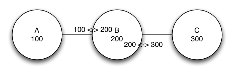
A switch that is capable of VLAN translation can map an ingress 802.1q frame's id from an external VLAN id to a local id and vice-versa on egress.

For instance, in the above figure, networks A, B, and C want to connect three different VLAN ids into a single circuit. In this case case network B configured its switches to map its neighbor's ids to its internal on ingress and back to the neighbor id on egress.
There seems to be a limited number of switches that support VLAN Mapping, one example is the Cisco 6500 series (which supports the command 'switchport vlan mapping' as shown here.
VLAN Tunneling (q-in-q)
It is often necessary to connect two remote networks at layer 2 through a third-party, such as a service provider. Or, to connect a campus lab to NLR through the campus and regional networks. VLAN tunnels (q-in-q) add a second VLAN id to the frame (called the outer tag), switches based on the outer tag, and then removes the outer tag at the other end of the tunnel. With a VLAN tunnel, a single VLAN circuit across a service provider can transit all 4096 VLAN ids between the customer network pops.

In the above figure, customer A has a west and east location, each with VLAN 100. Traffic from the customer has the outer tag 3028 added to it before it is switched through the provider network. Finally, the outer tag is removed when it is sent back to the other end of the customer circuit.
For more information about tunneling please see CISCO guide to VLAN tunneling
Connecting to GENI
To connect to GENI, you first need to identify the backbone network to connect to, and then you need to create a layer 2 path between your laboratory and the backbone. This section describes the available backbone networks to GENI and also provides an example network design.
GENI Transit Networks
The majority of GENI users will want to connect either to the GENI lambda on I2, NLR's FrameNet network, or the ION network (formerly DCN) on I2.
Internet2 GENI Wave
The I2 PoPs are on the map on this page. The "IP" nodes are the locations that support the GENI wave.
NLR FrameNet
NLR's FrameNet network provides VLANs across the NLR network without dedicated bandwidth. They support point-to-point VLANs today and intend to support multi-point in the future. To try a demonstration of FrameNet and to see a list of available PoPs, try using the SHERPA demonstration mentioned in the beginning of the FrameNet FAQ mentioned here.
I2 ION
The I2 ION project allows you to create temporary point-to-point VLANs that provide dedicated bandwidth. The ION service supports VLAN translation. For a list of PoPs that support ION, please login to the demonstration page described here and look at the list of available sources and destinations.
Getting there
Your campus might already have an NLR or I2 connection, but it is likely a layer 3 connection. You need to arrange to have vlans run from your aggregate's resources, across the campus network, possibly across a regional network, to the NLR or I2 hand-off.
This section provides example network designs that may be applicable to your school.
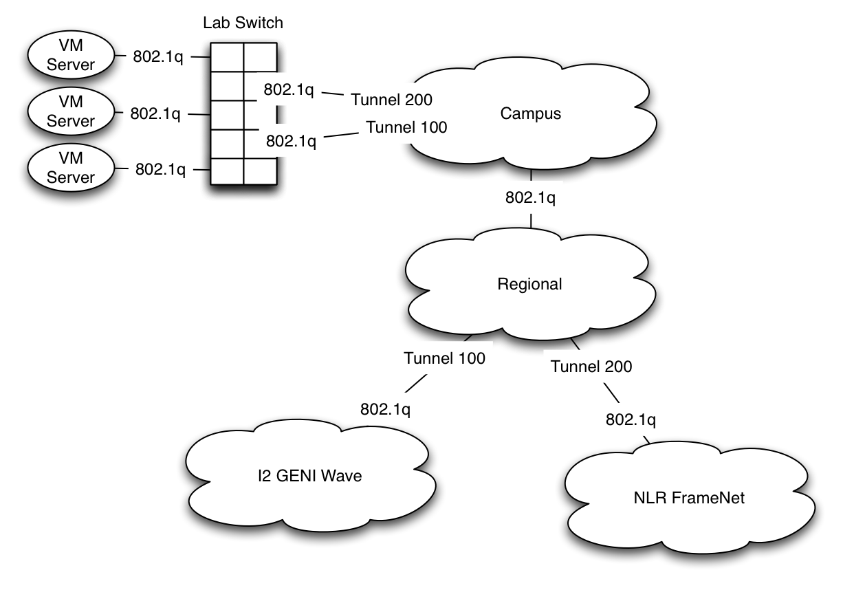
Example 1

In this example, the aggregate wants to connect to NLR and I2 but has to traverse its department, campus, and regional networks to get to them. The aggregate has a tunnel to each backbone. This means that the campus and regional's only have to configure a single VLAN for each backbone. Next, the aggregate maps the VLANs from the backbones to its own local VLAN ids.
This is a relatively simple process with only one backbone. The campus can end the tunnel and the aggregate's switch can map the backbone's VLAN to a local one. With multiple backbones, the VLANs from the backbones could collide. Therefore, each tunnel would have to terminate in a separate switch of the aggregate's where the VLAN can be mapped.
Attachments (4)
- vlan_tunnel.png (179.2 KB) - added by 14 years ago.
- vlan_tunnel_sp.png (70.5 KB) - added by 14 years ago.
- vlan_mapping.png (36.2 KB) - added by 14 years ago.
- agg_setup.png (162.2 KB) - added by 14 years ago.
Download all attachments as: .zip