
(If the install fails, you may first run: sudo apt-get update. In some cases, you may need to first run: sudo add-apt-repository ppa:openjdk-r/ppa followed by: sudo apt-get update.)
 }}}
We use the same PI control for load balancing as in [wiki:GENIExperimenter/Tutorials/NFV/Ryu/LoadBalancePIwithRyu Experiment 2], and you can find details about the PI control there.
== (1) RINA Distributed Application ==
(Same as Part (1) RINA Distributed Application in [wiki:GENIExperimenter/Tutorials/NFV/Ryu/LoadBalancePIwithRyu Experiment 2]. )
First we will run a RINA distributed application to collect the VNF load information on the controller node.
{{{
#!html
}}}
We use the same PI control for load balancing as in [wiki:GENIExperimenter/Tutorials/NFV/Ryu/LoadBalancePIwithRyu Experiment 2], and you can find details about the PI control there.
== (1) RINA Distributed Application ==
(Same as Part (1) RINA Distributed Application in [wiki:GENIExperimenter/Tutorials/NFV/Ryu/LoadBalancePIwithRyu Experiment 2]. )
First we will run a RINA distributed application to collect the VNF load information on the controller node.
{{{
#!html
| |
We need Java installed on the VNF1, VNF2 and controller nodes to run the RINA application. Check if Java is installed using: java -version. If not, install java on VNF1, VNF2 and controller nodes in new windows (Type Ctrl-C to exit netcat on the sources and destination). To install Java, execute: sudo apt-get install openjdk-7-jdk (If the install fails, you may first run: sudo apt-get update. In some cases, you may need to first run: sudo add-apt-repository ppa:openjdk-r/ppa followed by: sudo apt-get update.) |
 }}}
In the VNF2 window, execute:
- ''' cd ~/VNF2'''
- ''' nano ipcVNF2.properties '''
At the bottom of the file, again change the '''''rina.dns.name''''' and '''''rina.idd.name''''' to the IP address of the controller.
In the controller window, execute:
- '''cd ~/Control/RINA'''
- '''nano ipcControl.properties'''
At the bottom of the file, again change the ''''rina.dns.name'''' and ''''rina.idd.name'''' to the IP address of the controller.
6. To run the RINA application, follow these steps (make sure you installed Java as noted above):
o In the controller window, execute the following commands:
- ''' cd ~/Control/RINA/'''
- ''' ./run_controller.sh '''
o In the VNF1 window, execute the following commands:
- '''cd ~/VNF1/'''
- ''' ./run_VNF1.sh '''
o In the VNF2 window, execute the following commands:
- '''cd ~/VNF2/'''
- ''' ./run_VNF2.sh '''
You should see output on the controller window as shown below:
{{{
#!html
}}}
In the VNF2 window, execute:
- ''' cd ~/VNF2'''
- ''' nano ipcVNF2.properties '''
At the bottom of the file, again change the '''''rina.dns.name''''' and '''''rina.idd.name''''' to the IP address of the controller.
In the controller window, execute:
- '''cd ~/Control/RINA'''
- '''nano ipcControl.properties'''
At the bottom of the file, again change the ''''rina.dns.name'''' and ''''rina.idd.name'''' to the IP address of the controller.
6. To run the RINA application, follow these steps (make sure you installed Java as noted above):
o In the controller window, execute the following commands:
- ''' cd ~/Control/RINA/'''
- ''' ./run_controller.sh '''
o In the VNF1 window, execute the following commands:
- '''cd ~/VNF1/'''
- ''' ./run_VNF1.sh '''
o In the VNF2 window, execute the following commands:
- '''cd ~/VNF2/'''
- ''' ./run_VNF2.sh '''
You should see output on the controller window as shown below:
{{{
#!html
 }}}
{{{
#!html
}}}
{{{
#!html
| |
The RINA application on VNF1 and VNF2 should be run as soon as possible after the RINA application on the controller is started. If you wait for too long, you will get null values for CPU usage, as the controller's RINA app is not able to subscribe to the CPU load of the VNFs. If this is the case, you should restart all RINA processes. |
 |
To stop all RINA processes running on a VM, run killall -v java |
| |
The PI-controller gets the load information of VNF1 and VNF2 using RINA's distributed application and makes the load balancing decision. |
 |
| Block diagram of the PI-controller NFV system. System load L and target load T(s)=T/s of VNF1 is used to compute X, i.e. ratio of traffic diverted to VNF2. K` = K/T. |
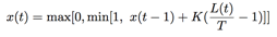 }}}
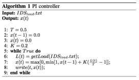
The code for the PI controller is based on the following algorithm. Input ''IDS,,load,,.txt'' is the file generated by the RINA distributed application. This file has load information of the VNFs.
{{{
#!html
}}}
The code for the PI controller is based on the following algorithm. Input ''IDS,,load,,.txt'' is the file generated by the RINA distributed application. This file has load information of the VNFs.
{{{
#!html
 }}}
1. To run the PI-controller, open a new controller window and execute:
- ''' cd ~/Control/PI_controller '''
- ''' python PI_controller.py ~/Control/RINA/NFV1.txt'''
Note that here we are directing ''PI_controller.py'' to the ''NFV1.txt'' file that is constantly updated by the RINA distributed application with the load information of VNFs.
2. You should see the VNF state information printed on the screen. A sample output is shown below.
{{{
#!html
}}}
1. To run the PI-controller, open a new controller window and execute:
- ''' cd ~/Control/PI_controller '''
- ''' python PI_controller.py ~/Control/RINA/NFV1.txt'''
Note that here we are directing ''PI_controller.py'' to the ''NFV1.txt'' file that is constantly updated by the RINA distributed application with the load information of VNFs.
2. You should see the VNF state information printed on the screen. A sample output is shown below.
{{{
#!html
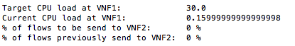 }}}
Here the target load on VNF1 is 30.0% of CPU usage, i.e. if the CPU load on VNF1 is more than 30.0%, traffic flows will be diverted to VNF2. The `current CPU load` shows the load on VNF1. The next line of the output shows the percentage of flows that will be directed to VNF2 and the last line shows the flows that were being directed to VNF2 before the current control update.
'''Do not close this window; leave the PI controller running.'''
== (3) PI-based Ryu Controller ==
(Same as Part (3) PI-based Ryu Controller in [wiki:GENIExperimenter/Tutorials/NFV/Ryu/LoadBalancePIwithRyu Experiment 2]. )
Now we will run the Ryu controller that will get the load balancing decision from the PI-controller and direct the flows accordingly.
1. First we will update the ''port.config'' file to direct the controller to the ''NFV_ratio_PI.txt'' file generated by the PI-controller, which has the load balancing decision information. In a new controller window, execute:
- ''' nano /tmp/ryu/ryu/app/nfv.config'''
o Change the value of '''controller_type''' to '''PI''' [[BR]]
o Change the value of '''''file_path_pi''''' to the text file that has the PI controller`s output.[[BR]]
'''''/users//Control/PI_controller/NFV_ratio_PI.txt'''''[[BR]]
Change the '''''''''' to your user name.[[BR]]
2. Now we can run the Ryu controller. Execute
- ''' /tmp/ryu/bin/ryu-manager --verbose /tmp/ryu/ryu/app/nfv_controller.py'''
== (4) Run Snort ==
''' Note: keep the RINA application processes, PI controller process and PI-based Ryu controller process from the previous 3 steps running in the background. '''
1. We need to first install our own Snort rule on Snort, so that it can detect the intrusion traffic specified in our rule.
To install our own rule and configure Snort, in separate windows for VNF1 and VNF2, execute the following commands:
- ''' cd ~ '''
- ''' wget !http://csr.bu.edu/rina/grw-bu2016/nfv_ryu/snort/config_snort.sh '''
- ''' chmod 755 config_snort.sh '''
- ''' ./config_snort.sh '''
Here we use a simple rule where all ICMP traffic to the ''destination'' node is considered as intrusion traffic, and the rule is specified as follows:
''' alert icmp any any -> 10.10.1.5 any (msg:"ICMP traffic found to Destination";sid:1000001;) '''
in the file ''' /etc/snort/rules/my.rules'''.
2. We then run Snort IDS on VNF1 and VNF2. In separate windows for VNF1 and VNF2, execute the following command:
- ''' sudo /usr/local/bin/snort -A full -dev -c /etc/snort/snort.conf -i eth1'''
''' Note: exit from previous instances of snort if they are still running from earlier experiments before you run this instance of snort. '''
''' Note: this command is different from [wiki:GENIExperimenter/Tutorials/NFV/Ryu/LoadBalancePIwithRyu Experiment 2], where the file ''/etc/snort/snort.conf '' specifies which rule files to load. '''
When Snort detects intrusion traffic, it will save the alert messages into the file '' /var/log/snort/alert''. The RINA distributed application keeps reading this alert file, and pass any intrusion information to the Ryu controller which will block the intrusion traffic.
''' Note: If you want to re-run this experiment, make sure to remove both files: '' /var/log/snort/alert'' on both VNF nodes, and ''/tmp/attacker.txt'' on the controller node. '''
== (5) Generate Regular and Intrusion Traffic ==
1. In a separate window for destination, start the netcat server by running:
- ''' nc -u -l 5000 '''
2. In another separate window for s1, start the netcat client by running:
- ''' nc -u destination 5000'''
3. Type something on the s1 window and you should see it on the destination window.
4. In another separate window for s1, we will generate attack traffic, which in our case are ICMP messages. To send ICMP messages to the destination, run the following ping command:
- ''' ping destination'''
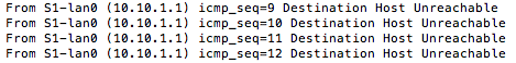
The first few ping messages are able to reach destination since it takes some time for the controller to get the intrusion detection results from the VNFs via the RINA distributed application, but after a few seconds, all following ping messages will not be able to reach the destination, and you should see the following output:
{{{
#!html
}}}
Here the target load on VNF1 is 30.0% of CPU usage, i.e. if the CPU load on VNF1 is more than 30.0%, traffic flows will be diverted to VNF2. The `current CPU load` shows the load on VNF1. The next line of the output shows the percentage of flows that will be directed to VNF2 and the last line shows the flows that were being directed to VNF2 before the current control update.
'''Do not close this window; leave the PI controller running.'''
== (3) PI-based Ryu Controller ==
(Same as Part (3) PI-based Ryu Controller in [wiki:GENIExperimenter/Tutorials/NFV/Ryu/LoadBalancePIwithRyu Experiment 2]. )
Now we will run the Ryu controller that will get the load balancing decision from the PI-controller and direct the flows accordingly.
1. First we will update the ''port.config'' file to direct the controller to the ''NFV_ratio_PI.txt'' file generated by the PI-controller, which has the load balancing decision information. In a new controller window, execute:
- ''' nano /tmp/ryu/ryu/app/nfv.config'''
o Change the value of '''controller_type''' to '''PI''' [[BR]]
o Change the value of '''''file_path_pi''''' to the text file that has the PI controller`s output.[[BR]]
'''''/users//Control/PI_controller/NFV_ratio_PI.txt'''''[[BR]]
Change the '''''''''' to your user name.[[BR]]
2. Now we can run the Ryu controller. Execute
- ''' /tmp/ryu/bin/ryu-manager --verbose /tmp/ryu/ryu/app/nfv_controller.py'''
== (4) Run Snort ==
''' Note: keep the RINA application processes, PI controller process and PI-based Ryu controller process from the previous 3 steps running in the background. '''
1. We need to first install our own Snort rule on Snort, so that it can detect the intrusion traffic specified in our rule.
To install our own rule and configure Snort, in separate windows for VNF1 and VNF2, execute the following commands:
- ''' cd ~ '''
- ''' wget !http://csr.bu.edu/rina/grw-bu2016/nfv_ryu/snort/config_snort.sh '''
- ''' chmod 755 config_snort.sh '''
- ''' ./config_snort.sh '''
Here we use a simple rule where all ICMP traffic to the ''destination'' node is considered as intrusion traffic, and the rule is specified as follows:
''' alert icmp any any -> 10.10.1.5 any (msg:"ICMP traffic found to Destination";sid:1000001;) '''
in the file ''' /etc/snort/rules/my.rules'''.
2. We then run Snort IDS on VNF1 and VNF2. In separate windows for VNF1 and VNF2, execute the following command:
- ''' sudo /usr/local/bin/snort -A full -dev -c /etc/snort/snort.conf -i eth1'''
''' Note: exit from previous instances of snort if they are still running from earlier experiments before you run this instance of snort. '''
''' Note: this command is different from [wiki:GENIExperimenter/Tutorials/NFV/Ryu/LoadBalancePIwithRyu Experiment 2], where the file ''/etc/snort/snort.conf '' specifies which rule files to load. '''
When Snort detects intrusion traffic, it will save the alert messages into the file '' /var/log/snort/alert''. The RINA distributed application keeps reading this alert file, and pass any intrusion information to the Ryu controller which will block the intrusion traffic.
''' Note: If you want to re-run this experiment, make sure to remove both files: '' /var/log/snort/alert'' on both VNF nodes, and ''/tmp/attacker.txt'' on the controller node. '''
== (5) Generate Regular and Intrusion Traffic ==
1. In a separate window for destination, start the netcat server by running:
- ''' nc -u -l 5000 '''
2. In another separate window for s1, start the netcat client by running:
- ''' nc -u destination 5000'''
3. Type something on the s1 window and you should see it on the destination window.
4. In another separate window for s1, we will generate attack traffic, which in our case are ICMP messages. To send ICMP messages to the destination, run the following ping command:
- ''' ping destination'''
The first few ping messages are able to reach destination since it takes some time for the controller to get the intrusion detection results from the VNFs via the RINA distributed application, but after a few seconds, all following ping messages will not be able to reach the destination, and you should see the following output:
{{{
#!html
 }}}
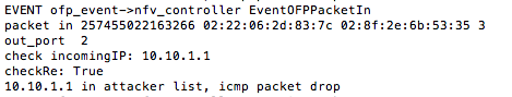
5. Type something on the s1 window for netcat and you should NOT see it on the destination window. If you go to the controller window which runs the Ryu controller, you can see that all traffic from the attacker is dropped with the following output:
{{{
#!html
}}}
5. Type something on the s1 window for netcat and you should NOT see it on the destination window. If you go to the controller window which runs the Ryu controller, you can see that all traffic from the attacker is dropped with the following output:
{{{
#!html
 }}}
6. Restart the netcat server on the destination by running:
- ''' nc -u -l 5000 '''
7. In another separate window for s2, start the netcat client by running:
- ''' nc -u destination 5000'''
Notice that using the netcat client side on s2, all messages are able to reach the destination since s2 traffic is not blocked. However, no traffic from s1 reaches the destination since s1 is blocked.
== Next Experiment ==
== [wiki:GENIExperimenter/Tutorials/NFV/Ryu/HandlingIntrusionwithRyu-portscanning Experiment 4: Handling Intrusion with Ryu Controller: Port Scanning Attack] ==
}}}
6. Restart the netcat server on the destination by running:
- ''' nc -u -l 5000 '''
7. In another separate window for s2, start the netcat client by running:
- ''' nc -u destination 5000'''
Notice that using the netcat client side on s2, all messages are able to reach the destination since s2 traffic is not blocked. However, no traffic from s1 reaches the destination since s1 is blocked.
== Next Experiment ==
== [wiki:GENIExperimenter/Tutorials/NFV/Ryu/HandlingIntrusionwithRyu-portscanning Experiment 4: Handling Intrusion with Ryu Controller: Port Scanning Attack] ==